در این پروژه می خواهیم یک ربات کدینگ (coding robot) با استفاده از آردوینو و زبان برنامه نویسی Tangible طراحی کنیم بطوریکه مسیر مشخصی که از قبل کدگذاری شده را طی کند تا به هدف مورد نظر برسد.
Tangible چیست و چه کاربردی دارد؟
برنامه نویسی Tangible یک زبان مبتنی بر متن است و برای کودکان موقعیتی را فراهم می کند تا بدون استفاده از صفحه نمایش درگیر برنامه نویسی شوند.
امروزه تهیه وسایل و اسباب بازی برای کودکان که آنها را ترغیب کند تا همانند برنامه های درسی STEAM (یک رویکرد آموزشی برای یادگیری است که از علوم، فناوری، مهندسی، هنر و ریاضیات برای پرسش، گفتگو و تفکر انتقادی دانش آموزان استفاده می کند) به برنامه نویسی بپردازند، مساله بسیار مهمی است. کد نویسی به زبان Tangible یک روش جدید برای برنامه نویسی کودکان می باشد.
کار با آن بسیار ساده است و کودکان را برای کدنویسی آماده می کند. در واقع موقعیتی برای کودکان فراهم می کند تا بدون نیاز به دانشی در مورد ساختار زبان های برنامه نویسی، کد نویسی کنند. همچنین نیازی به صفحه نمایش برای برنامه نویسی نیست. زبان برنامه نویسی Tangible از نظر ساختاری شبیه به زبان های مبتنی بر متن (همانند زبان C++) است. اما به جای نوشتن دستورالعمل ها، یکسری جعبه یا کلیدهایی در کنار هم قرار می گیرند که هر کلید یا جعبه یک دستورالعمل یا کد همانند ساختارهای کنترلی (…,if,for) و دستورات را بیان می کند. کودکان می توانند برای پیاده سازی یک برنامه، بلوک ها را کنار هم قرار دهند یا کلیدها را به روش های مختلف فشار دهند.
چگونه ربات کدینگ Tangible را طراحی کنیم؟
کنسول کد نویسی Tangible معمولاً برای ساخت و اجرای عملکردهای coding robot استفاده می شود. هدف ما در این پروژه، ساخت ربات کدینگ tangible است. بنابراین، کودکان به راحتی می توانند ربات خود با دستورالعمل های مختلف همچون حرکت در یک مسیر مشخص یا برخورد با اشیا را برنامه نویسی کنند. اگر یک ماژیک به ربات وصل کنید، می توان ربات کدینگ Tangible را به شکلی برنامه نویسی کنید تا الگوهای نقاشی زیبایی بر روی کاغذ ایجاد کند. همچنین می توانید به ربات، چراغهای ال ای دی وصل کنید تا همراه با چرخش به دور خود، چراغها روشن شوند.
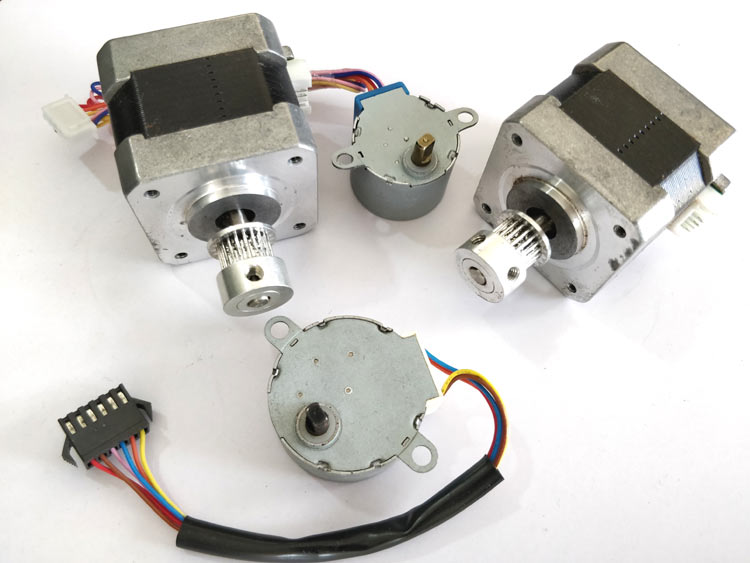
ربات کدینگ را با استفاده از کنسول کد نویسی tangible، پرینتر سه بعدی برای چاپ قطعات مکانیکی ربات، دو موتور گیربکس DC ، یک بورد آردوینو ، ماژول وایرلس NRF و پنج تک سوئیچ طراحی کنید. همچنین می توانید با فشار دادن کلیدهای رنگی روی کنسول کد نویسی tangible، ربات coding robot را برای حرکت کردن در یک مسیر خاص کد نویسی کنید.
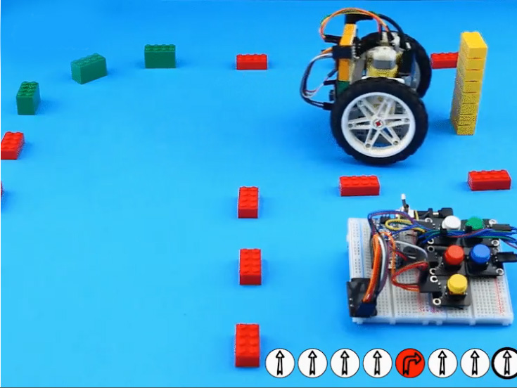
کنسول کد گذاری و ربات در تصویر زیر نشان داده شده اند. هنگامیکه کاربر سوئیچ ها را به صورتهای مختلف فشار می دهد، یک برنامه ایجاد می شود و در آردوینو ذخیره می شود. سپس دستورات کد نویسی از طریق یک کانال ارتباطی که با استفاده از ماژول وایرلس NRFایجاد می شود، به سمت ربات ارسال می شوند.
ساختار بدنه ربات کدینگ Tangible
ساختار بدنه coding robot را با استفاده از پرینتر سه بعدی چاپ کنید و به هم وصل نمایید. سپس دو موتور DC را به چرخهای ربات کدینگ tangible وصل کنید تا ربات را در مسیر تعیین شده حرکت دهد.
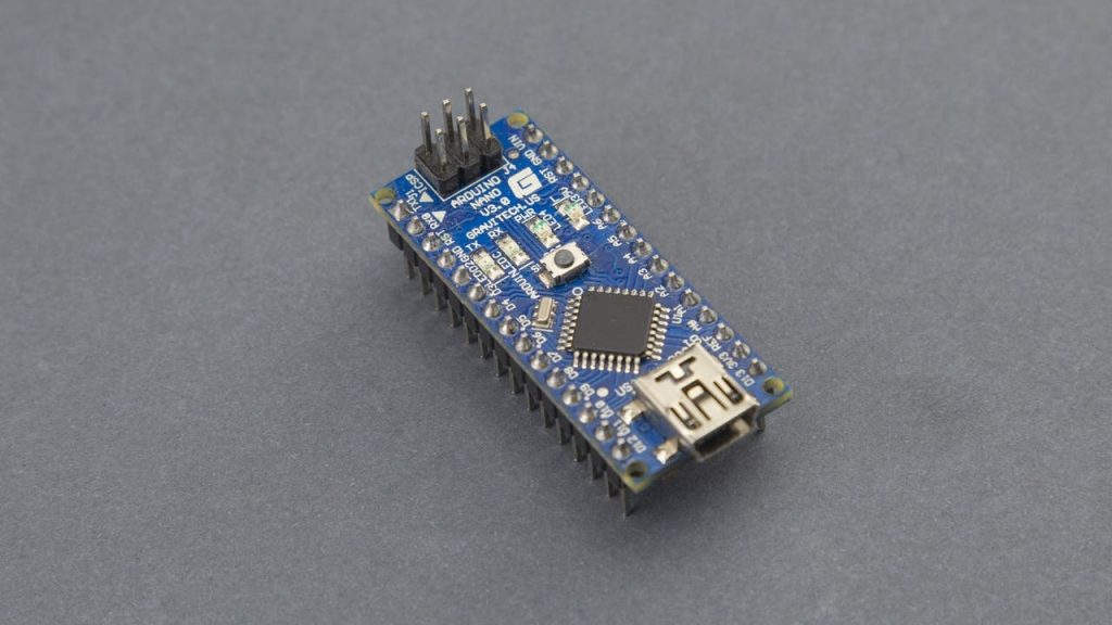
در مرحله بعدی، ماژول آردوینو نانو را که مغز coding robot محسوب می شود را به برد اضافه کنید. این ماژول از یک میکروپروسسور بسیار کوچک و قدرتمند تشکیل شده که برای رباتهای کم وزن و کوچک مناسب است.
موتورهای مختلف، سنسورها و ال ای دی ها را می توان به راحتی به میکروکنترلر آردوینو وصل کرد. این ویژگی سبب شده تا بتوان عملکرد ربات را به راحتی توسعه داد. به عنوان مثال همانطور که در تصویر زیر می بینید، می توانید به ربات یک ماژیک وصل کنید تا بر روی کاغذ نقاشی بکشد یا اینکه چراغ های ال ای دی به آن وصل کنید تا نورهای رنگی ایجاد کند.
طبق تصویر زیر ربات کدینگ tangible دارای پنج تک سوئیچ برای کنترل حرکت است که می تواند با استفاده از آنها به جلو (کلید سفید رنگ)، عقب (کلید سبز)، حرکت به راست (کلید قرمز)، حرکت به چپ (کلید آبی) و دویدن (کلید زرد) حرکت کند. سپس سیگنالهای دستوری با استفاده از ماژول NRF به ربات ارسال می شوند. دستورات بسیار ساده هستند و شما می توانید به راحتی این ربات را طراحی کنید.
اتصالات مکانیکی ربات کدینگ

در این بخش ساختار بدنه ربات که شامل چرخهای جلو، عقب و قطعات الکترونیکی می باشد را با هم طراحی می کنیم. قطعات ربات را همانند ویدیویی که در زیر آمده، گام به گام بهم وصل کنید.
برای قرار دادن موتورهای DC در جای مناسب و اتصال به چرخ ها باید یک جفت شافت و یک جایگاه مناسب برای نگه داشتن آنها با استفاده از پرینتر سه بعدی طراحی و چاپ کنید
اتصالات الکترونیکی ربات
برای طراحی ربات کدینگ باید هر دو مدار کنسول کد گذاری و ربات را طراحی کنید. تصویر دیاگرام این مدارها در زیر آمده است. مطابق با تصویر دیاگرام و ویدیوی زیر مدارهای ربات و کنسول کد گذاری tangible را با دقت طراحی کنید.
برنامه نویسی ربات
پس از آماده سازی بخش مکانیکی و الکترونیکی ربات کدینگ tangible ، حال نوبت به برنامه نویسی آن است. کد ربات و کنسول tangible زیر را دانلود و بر روی آردوینو و کنسول آپلود کنید.
کد ربات :
/*
Tangible Coding Robot
The idea:
In this project, we will show you how to make a tangible programmable robot out of Lego Technic pieces,
Arduino boards, off-the-shelf DC motors, and NRF communication modules.
The current project uses two Arduino Nano boards as the main controller of the
robot and the programming console, respectively
The circuit:
- In this circuit, an Arduino Nano is used. Any other types of Arduino
can be used of course but do not forget to change the pin configurations
if you want to change the circuit on your preference.
Visit the Tart Robotics blog for more information:
https://www.tartrobotics.com/blog
*/
#define motorRightA A0
#define motorRightB A1
#define motorRightPWM 6
#define motorLeftA A2
#define motorLeftB A3
#define motorLeftPWM 5
#include <SPI.h>
#include <nRF24L01.h>
#include <RF24.h>
#include <Servo.h>
RF24 radio(9, 10); // CE, CSN
// Setup Adafriut Neopixel LED Ring
#include <Adafruit_NeoPixel.h>
#define PIXELSPIN 4
#define NUMPIXELS 16
Adafruit_NeoPixel pixels = Adafruit_NeoPixel(NUMPIXELS, PIXELSPIN, NEO_GRB + NEO_KHZ800);
const byte address[6] = "00010";
const int motorSpeed = 80, straightTimeDelay = 600, turningTimeDelay = 560;
void setup() {
radio.begin();
radio.openReadingPipe(0, address);
radio.setPALevel(RF24_PA_MIN);
radio.startListening();
pixels.begin(); // Adafriut Neopixel begin
for (int i = 0; i < 17; i++) {
pixels.setPixelColor(i, pixels.Color(0, 0, 0));
pixels.show();
}
}
void loop() {
if (radio.available()) {
// Take and decode instructions
char instructions[50] = "";
radio.read(&instructions, sizeof(instructions));
for (int i = 0; i < sizeof(instructions); i++) {
char message = instructions[i];
stopTheRobot();
delay(200);
if (message == 'f') {
goForward();
} else if (message == 'b') {
goBackward();
} else if (message == 'r') {
goRight();
} else if (message == 'l') {
goLeft();
} else if (message == 's') {
stopTheRobot();
break;
}
}
}
}
void goForward() {
digitalWrite(motorRightA, LOW);
digitalWrite(motorRightB, HIGH);
analogWrite(motorRightPWM, motorSpeed);
digitalWrite(motorLeftA, HIGH);
digitalWrite(motorLeftB, LOW);
analogWrite(motorLeftPWM, motorSpeed);
pixels.setPixelColor(6, pixels.Color(200, 200, 190));
pixels.setPixelColor(7, pixels.Color(200, 200, 190));
pixels.setPixelColor(8, pixels.Color(200, 200, 190));
pixels.setPixelColor(9, pixels.Color(200, 200, 190));
pixels.setPixelColor(10, pixels.Color(200, 200, 190));
pixels.show();
delay(straightTimeDelay);
for (int i = 0; i < 17; i++) {
pixels.setPixelColor(i, pixels.Color(0, 0, 0));
pixels.show();
}
}
void goBackward() {
digitalWrite(motorRightA, HIGH);
digitalWrite(motorRightB, LOW);
analogWrite(motorRightPWM, motorSpeed);
digitalWrite(motorLeftA, LOW);
digitalWrite(motorLeftB, HIGH);
analogWrite(motorLeftPWM, motorSpeed);
pixels.setPixelColor(0, pixels.Color(0, 200, 0));
pixels.setPixelColor(1, pixels.Color(0, 200, 0));
pixels.setPixelColor(2, pixels.Color(0, 200, 0));
pixels.setPixelColor(14, pixels.Color(0, 200, 0));
pixels.setPixelColor(15, pixels.Color(0, 200, 0));
pixels.show();
delay(straightTimeDelay);
for (int i = 0; i < 17; i++) {
pixels.setPixelColor(i, pixels.Color(0, 0, 0));
pixels.show();
}
}
void goLeft() {
digitalWrite(motorRightA, LOW);
digitalWrite(motorRightB, HIGH);
analogWrite(motorRightPWM, motorSpeed);
digitalWrite(motorLeftA, LOW);
digitalWrite(motorLeftB, HIGH);
analogWrite(motorLeftPWM, motorSpeed);
pixels.setPixelColor(2, pixels.Color(0, 0, 210));
pixels.setPixelColor(3, pixels.Color(0, 0, 210));
pixels.setPixelColor(4, pixels.Color(0, 0, 210));
pixels.setPixelColor(5, pixels.Color(0, 0, 210));
pixels.setPixelColor(6, pixels.Color(0, 0, 210));
pixels.show();
delay(straightTimeDelay);
for (int i = 0; i < 17; i++) {
pixels.setPixelColor(i, pixels.Color(0, 0, 0));
pixels.show();
}
}
void goRight() {
digitalWrite(motorRightA, HIGH);
digitalWrite(motorRightB, LOW);
analogWrite(motorRightPWM, motorSpeed);
digitalWrite(motorLeftA, HIGH);
digitalWrite(motorLeftB, LOW);
analogWrite(motorLeftPWM, motorSpeed);
pixels.setPixelColor(10, pixels.Color(200, 0, 0));
pixels.setPixelColor(11, pixels.Color(200, 0, 0));
pixels.setPixelColor(12, pixels.Color(200, 0, 0));
pixels.setPixelColor(13, pixels.Color(200, 0, 0));
pixels.setPixelColor(14, pixels.Color(200, 0, 0));
pixels.show();
delay(straightTimeDelay);
for (int i = 0; i < 17; i++) {
pixels.setPixelColor(i, pixels.Color(0, 0, 0));
pixels.show();
}
}
void stopTheRobot() {
digitalWrite(motorRightA, HIGH);
digitalWrite(motorRightB, HIGH);
analogWrite(motorRightPWM, 0);
digitalWrite(motorLeftA, HIGH);
digitalWrite(motorLeftB, HIGH);
analogWrite(motorLeftPWM, 0);
}
کد کنسول ربات :
/*
Tangible Coding Console
The idea:
In this project, we will show you how to make a tangible programmable robot out of Lego Technic pieces,
Arduino boards, off-the-shelf DC motors, and NRF communication modules.
The current project uses two Arduino Nano boards as the main controller of the
robot and the programming console, respectively
The circuit:
- In this circuit, an Arduino Nano is used. Any other types of Arduino
can be used of course but do not forget to change the pin configurations
if you want to change the circuit on your preference.
Visit the Tart Robotics blog for more information:
https://www.tartrobotics.com/blog
*/
#define forward_button 8
#define backward_button 4
#define right_button 7
#define left_button 5
#define startstop_button 6
#define buzzerPin A0
#define auxGnd A2 //auxiliary ground pin
#include <SPI.h>
#include <nRF24L01.h>
#include <RF24.h>
RF24 radio(9, 10); // CE, CSN
const byte address[6] = "00010";
void setup() {
radio.begin();
radio.openWritingPipe(address);
radio.setPALevel(RF24_PA_MIN);
radio.stopListening();
pinMode(auxGnd, OUTPUT);
pinMode(buzzerPin, OUTPUT);
digitalWrite(auxGnd, LOW);
}
void loop() {
//Take the instructions (50 instructions in a row maximum)
char instructions[50];
for (int i = 0; i < sizeof(instructions); i++)
instructions[i] = NULL;
boolean runTheProgram = false;
int i = 0;
while (i < sizeof(instructions)) {
buzz(100);
while (true) {
if (!digitalRead(forward_button)) {
while (!digitalRead(forward_button));
instructions[i] = 'f';
break;
} else if (!digitalRead(backward_button)) {
while (!digitalRead(backward_button));
instructions[i] = 'b';
break;
} else if (!digitalRead(left_button)) {
while (!digitalRead(left_button));
instructions[i] = 'r';
break;
} else if (!digitalRead(right_button)) {
while (!digitalRead(right_button));
instructions[i] = 'l';
break;
} else if (!digitalRead(startstop_button)) {
while (!digitalRead(startstop_button));
runTheProgram = true;
break;
}
}
i++;
if (runTheProgram)
break;
}
instructions[i] = 's';
buzz(800);
radio.write(&instructions, sizeof(instructions));
}
void buzz(int duration) {
digitalWrite(buzzerPin, HIGH);
delay(duration);
digitalWrite(buzzerPin, LOW);
}
دیاگرام مدار
قطعات مورد نیاز
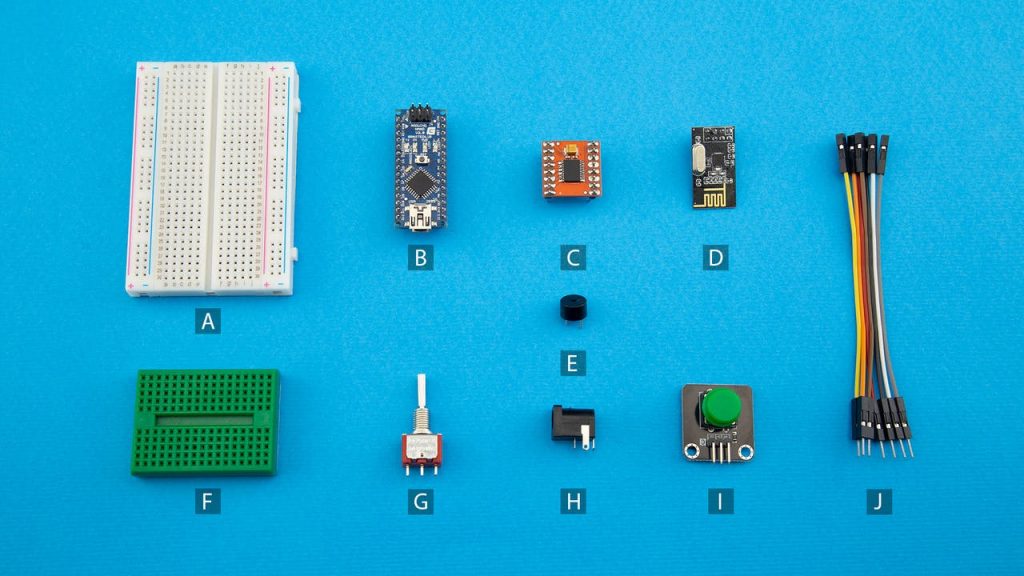
- 2x Breadboard, 83 x 52 x 9mm
- 2x Arduino Nano
- 1x Driver Motor
- 2x NRF 24L01, without Antenna Module
- 1x Buzzer, Active Type
- 1x Breadboard, Mini Size
- 1x Mini Switch, Toggle Type
- 2x Power Jack, Barrel Type
- 1x Pushbutton
- Male to Male Jumper Wire
- TT Gear Motor
- 3D Printed Gear Motor Housing
- Frame, 5×7 module
- Steel ball & ball bearing
- Wheel 61.6mm D. x 13.6mm Motorcycle
- T-Beam, 3×3 module
- Connector peg with friction, 2-module
- 3D Printed Lego-Compatible Coupling
- Beam, 9-module
- 2x M3 x 16 Machine Screw
- 1x M3 x 30 Machine Screw
- Double cross block, 3-module
- Axle, 2-module
- Connector peg with friction/axle, 2-module
- Beam, 7-module
- 2x M3 Nut
- 2x M3 Nut

